
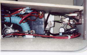

| Just getting started. This is a view down through the storage bin above the hidden compartment, with the acces hatch removed from the bin's floor. The front of the van is toward the top of the picture. The wall between the hidden compartment and the little low storage compartment aft of the fridge has been removed. You can see a thick, straight black line in the corner between the floor an d the left wall of that compartment - that's the wiring conduit that goes up to the bin behind the driver's seat. The blue hose is the water tank fill hose. Nestled in the curve of the hose (but closer to the floor) is the battery relay. To the right, on top of the hose, is the circuit breaker. The white area in the center of the pisture is the styrofoam platform for the battery. On the right, you can see the new, deeper silver electrical box for the 110V circuit breaker, 12V outlet, and invertor switch. The black cable heading out of the picture to the right is the male extension cord that will eventually be plugged into the invertor; it's wired into the brown 110V outlet electrical box. Below that, coming out of that same brown electrical box, is the female extension cord for the battery charger. At the bottom-left corner of the picture is the little "notch" (beneath the clear hoses) through which the manual battery connect switch can be reached. | |
|
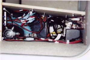
Now the battery's in, and the wall has been replaced. A little above the center of the picture is the red "positive" terminal of the battery. On the far left of the picture, near the top, you can just see the fuses sticking out from the new fuse panel. Above and to the right of that are the wires that come out of the fuse panel, all terminated with quick-disconnects and labeled with little white tags. Toward the bottom of the picture, you can see the red 8-gauge battery cable. On the far right, it curves toward the floor, where it goes out a hole (which you can't see). Near the right side of the pisture, in the center, is the 12V outlet for the invertor, mounted on the floow. It has a little wite "door" covering it, which in the picture looks kind of like an upside down white "U" with a black edge |
|
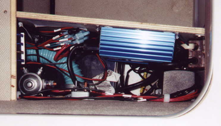
Now the charger's in. It's the new black cube on the lower right. The litte yellow rod in the center of the picture is the charger's in-line fuse holder. You can see the fuses in the new fuse panel a little better now, sticking out above a little white card that I used to label them. |
| The shiny blue box is the invertor. Everything's done..
|
|
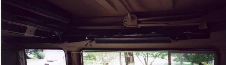
| Here's the passenger side of the van, with the curtain rail/shelf down, showing (dimly) some wiring. | |
|
You can just see the new light, looking like a black rectangle on the face of the air conditioner housing above Kevin. |
|
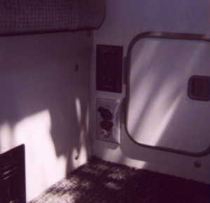
The electrical outlet looks the same as before, but now its bottom socket is connected to the invertor, rather than the shore tie. The original aluminum circuit breaker panel has been replaced with a gray plastic one (I chose gray to retain the original "look"), which now holds the new 12V outlet (top, with a cap over it), the power switch for the the invertor (middle, lights up red when on), and the original 110V circuit breaker (bottom). |
| Home |